
This is an old revision of the document!
LayerOne 2014 Badge Build
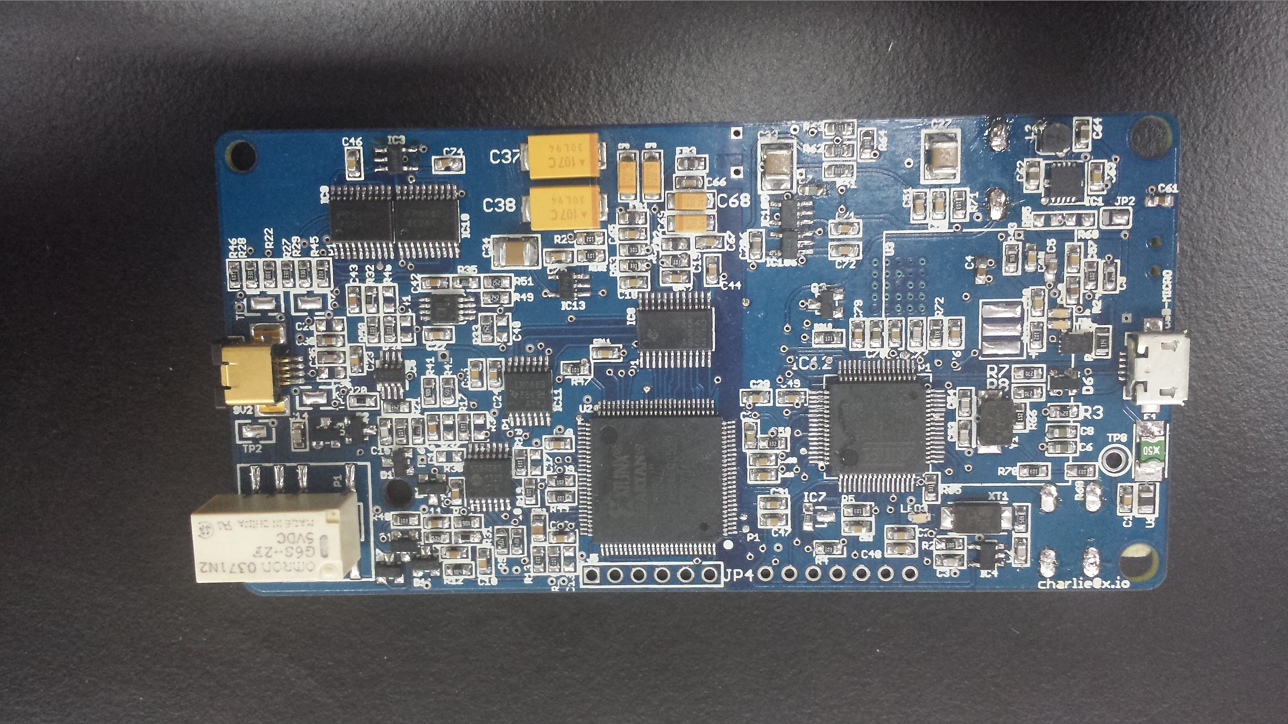
Please use pic above for orientation (click for larger image).
Notes
Please use the following board/schematic and NOT the svn:
Start with the parts on page 1 and page 2 of the schematic.
Don't place the battery yet.
Use hotair gun for IC1 and U$7.
Do not place (DNP) R55 and R60.
C9 should be a 0 ohm resistor (jumper).
R26 should be changed to 110K there is a reel in the box.
Jumper JP2 like so: 
IC3 is now a 500ma part. CAT6219-330TDGT3 Do not use same part as IC13.
If using micro usb, place it now. If using mini usb, wait till later as it goes on the bottom.
inject 5v in to 5V line at TP10, check at header pin for +3v3. ,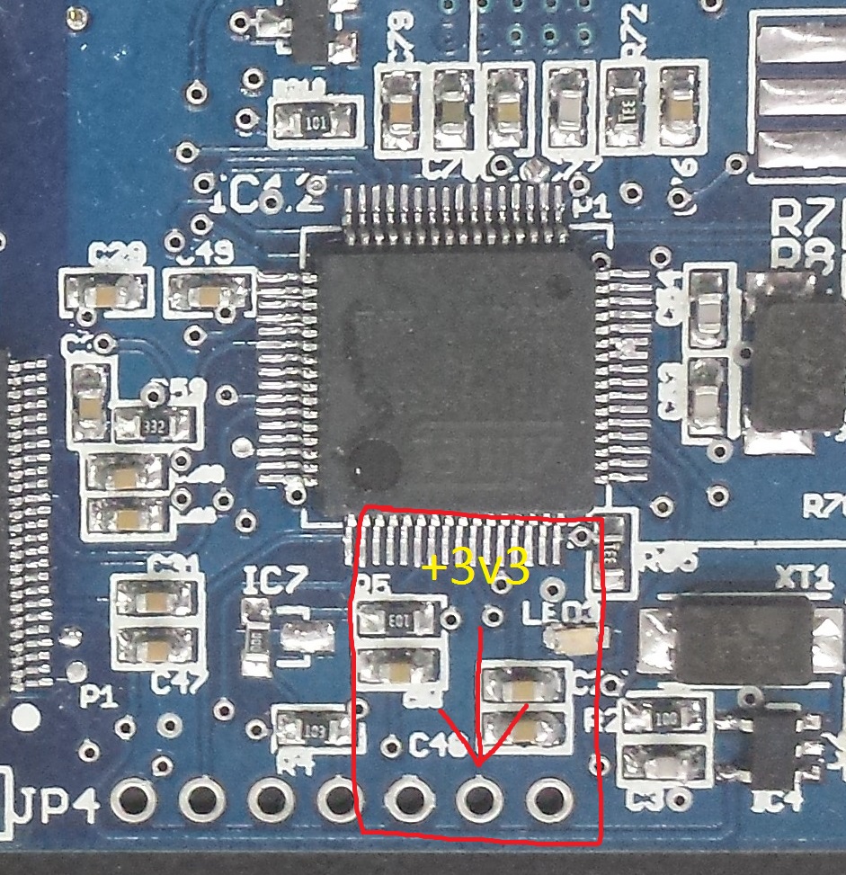
Once that checks out proceed to third page of schematic, and install the MCU (IC12) and the related parts.
Dont install the buttons and speaker yet, as they go on the bottom.
Short the two pins of IC7 with a zero ohm resistor like so: 
Now flash MCU with: L1 PM3OLED Firmware
Once again inject 5V in to TP10, test all the other voltages. 
Test point values:
TP18 - 3v3
TP19 - 2v5
TP20 - 1v2
Use the Silver SV2: 
Before installing the OLED display and battery, ensure the proxmark is properly working via USB by installing a jumper wire from F1 (PTC Fuse) to TP10 to provide 5V to the board. Plug into a computer and verify the correct USB VID/PID. This is also a good time to install required proxmark3 usb drivers and the proxmark3 application for your OS.
You need to install a jumper wire for the MOSI signal from the via near the buzzer to the correct pad of SJ1. Refer to the below photograph:
